Welcome to a new series!
Over the past few weeks, I developed an interest in studying digital circuits, and so I thought it would be interesting to write about this topic while learning about it. I first came across digital circuits, in the context of computing science, in a systems course in first year Computing at university. We covered very simple topics and didn't really drill into the implementation of the most basic components. In second year, there was a systems elective course for me that I passed on, and so have felt like I missed something.
More recently, Ben Eater's YouTube channel has been coming up on my recommendations quite a lot. He has a series of videos where he constructs an 8-bit computer from scratch, while introducing and explaining all the concepts as he goes. I've been watching his videos and they've definitely sparked my interest to learn more about the topic, as well as write about it. So here goes!
Fair warning: I do not claim to be an expert on this topic. What I am discussing here is what I have come to understand recently regarding digital circuits through my own personal research into the topic and my studies at university.
Representing data digitally
Let's start at the very beginning! How do we represent data on a circuit level?
Binary Numbers
To answer this question, we should be familiar with binary numbers. Typically, we represent numbers with a decimal numbering system, i.e. base 10. This means we have 10 symbols to use in representing numbers, 0-9. It also means we can break down numbers into weighted sums of powers of 10. For example the number $2304$ can be broken down like this:
$$ 2304 = 2\times 1000 + 3\times 100 + 0\times 10 + 4\times 1,$$
which is the same as saying:
$$ 2304 = (2\times 10^3) + (3\times 10^2) + (0\times 10^1) + (4\times 10^0) $$
In this same way of representing numbers in base 10, we can also represent numbers in base 2, i.e. binary, by only using two symbols: 0 and 1. This would mean counting in binary would go something like this:
| Decimal | 0 | 1 | 2 | 3 | 4 | 5 | 6 | 7 | 8 | 9 | 10 |
| Binary | 0 | 1 | 10 | 11 | 100 | 101 | 110 | 111 | 1000 | 1001 | 1010 |
Counting in binary.
A binary digit (a 0 or 1) is referred to as a bit.
Converting from binary to decimal
Consider the number 111011 in binary, and break it down the same way we broke down 2304, but this time using base 2:
$$ 111011_2 = (1\times 2^5) + (1\times 2^4) + (1\times 2^3) $$ $$ \hspace{3cm} + (0\times 2^2) + (1\times 2^1) + (1\times 2^0) $$
Evaluating this expression, we get:
$$ 111011_2 = 32 + 16 + 8 + 0 + 2 + 1 = 59 $$
This means that the number 111011 in binary represents the decimal number 59. There are many other bases of numbers which are useful in different situations like the octal numeral system (base 8), the hexadecimal system (base 16), etc, and they follow the same logic as above.
Converting from decimal to binary
What if we wanted to find the binary equivalent of a decimal number? We start by dividing that number by two, where we get a quotient and remainder. The remainder becomes the last digit of our binary number (we are certain to either get a remainder of 0 or 1 when dividing by two), and then we apply the same method to the quotient in order to get the next digit and so on until the quotient is zero.
Say we wanted to represent 2304 in binary. We divide it by 2: $2304/2 = 1152$, and the remainder is 0, so the last digit of the binary number is 0. Now divide the quotient by 2: $1152/2 = 576$. Again the remainder is 0 and so the second last digit is also 0. We do this until the quotient is 0:
$$ 2304/2 = 1152 + 0 $$ $$ 1152/2 = 576 + 0 $$ $$ 576/2 = 288 + 0 $$ $$ 288/2 = 144 + 0 $$ $$ 144/2 = 72 + 0 $$ $$ 72/2 = 36 + 0 $$ $$ 36/2 = 18 + 0 $$ $$ 18/2 = 9 + 0 $$ $$ 9/2 = 4 + 1 $$ $$ 4/2 = 2 + 0 $$ $$ 2/2 = 1 + 0 $$ $$ 1/2 = 0 + 1 $$
where the pluses on the right hand side represent the remainder of division rather than actual addition. And finally we arrive at the rather massive result of 100100000000.
But why did we study binary numbers?
Voltages
In an electric circuit, we represent data using voltages. A high voltage across a wire represents a 1 while a low or a zero voltage represents a 0. This is why we had to study binary numbers, because in the digital world all data has to be represented in a binary way.
Typically a high voltage, representing a 1, will be in the range of 2V to 5V while a low voltage, representing a 0, will be in the range 0V to 0.8V.
Creating and controlling a voltage
A battery is a component which creates a high electric potential through one of its ends and a low one through the other end, meaning that there will be a voltage across the wire connected to the positive end of the battery. We can use this to create high and low voltages. We should also introduce the concept of a ground here. A ground, in the context of electronics, is a reference point against which we measure other voltages. It is usually taken as having zero volts. This is also sometimes referred to as earth.
We can now create a high voltage by connecting the negative end of a battery to a ground and the positive end to a wire. But we can also go further than that by connecting the wire to a switch. A switch is simply a device which allows current to go through only when it's pressed. So when the switch is not pressed, the voltage across the wire is always low (zero).
The symbols for these electrical components are shown here:
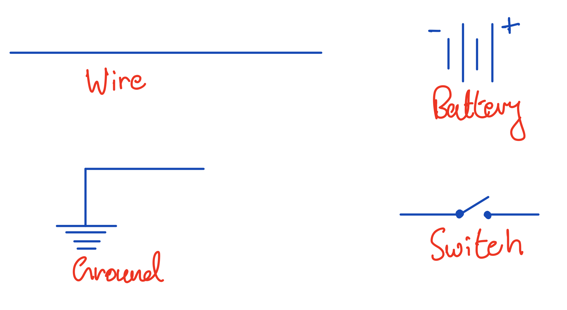
Basic circuit components.
Using these, we can build a simple circuit which has a switch for us to control the bit at the end of a wire:
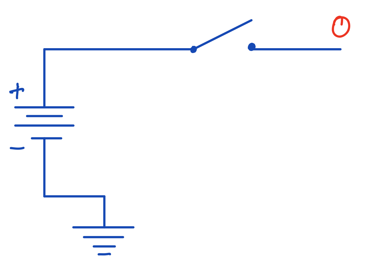
A circuit with an open switch. Because there's no voltage across the wire, then there is no potential difference between the wire and the ground and so the bit on the wire is 0.
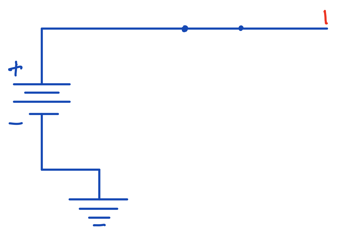
A circuit with a closed switch. Now there's a voltage across the wire and so the bit is 1.
You don't really need to worry too much about the intricacies of electricity here in order to carry on. If any physical concept becomes relevant as we discuss other ideas, I will make sure to explain it as we go.
Black Box
We now come to the concept of the black box, which is fairly important in electronics. A black box is some device which takes in an input signal (or multiple input signals), and gives out some output signal (or many output signals). These are usually developed such that the user of the black box doesn't really need to worry about the implementation of the device.
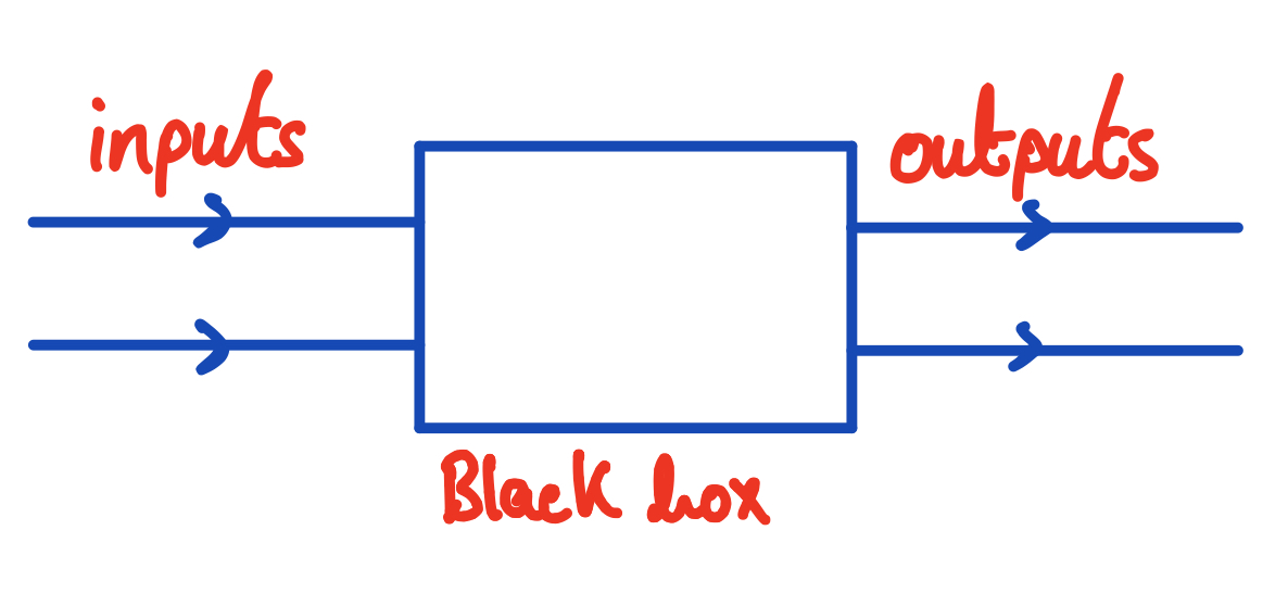
A black box.
In future articles we're going to be discussing many circuit components (logic gates, for example) which, after we discuss their implementation, can simply treat as black boxes.
And for now, we can discuss our first black box, the transistor.
Transistors
The transistor is going to be the one black box into whose implementation we won't be delving too deeply, because to really understand how a transistor works, one requires an understanding of the fundamentals of solid state physics.
A transistor takes two inputs, called the base and the collector and gives out one output, the emitter. Typically, the collector input will be some large current and the base input will be a small current. A transistor's basic function is to allow the large collector current to flow through to the emitter output if there is a current input at the base. The collector input will typically be coming from the power source of the circuit, whereas the base will be our digital input (either a high or low voltage representing a bit).
Here's the circuit symbol for the transistor:
![]()
Circuit symbol for a transistor. Note that the emitter is always the output with the arrow inside the circle (as you may see this diagram flipped vertically later on).
Let's now use this transistor to construct a circuit where we control a small current coming from a battery with a switch (like the one above), which is connected to the base input of a transistor in order to control a larger current coming from the main power source of the circuit:
![]()
A transistor in use in our circuit from before. When the switch is closed, current is allowed to flow through the base of the transistor and so the collector current can flow through to the emitter.
Conclusions
In this article, we started by discussing how data is represented in digital circuits with binary numbers and using high and low voltages to represents bits.
We also talked about the transistor, which is essentially a decision maker in circuit design because it lets us say do this (pass the collector current) only if something (a current goes through the base) happens. We will use transistors, in different combinations, to construct other more complicated circuit elements (like basic logic gates), in future articles.
Closing remarks
I hope you've found this article an interesting and entertaining read! If you have any recommendations or feedback about the content, please feel free to leave a comment below or contact me through the website.
Feel free to also tweet me: @_devdude.
Thanks for reading!
Related
You may also be interested in:
React Native: Modal Screens with React Navigation
Particle Physics, Part 1: Why is the Standard Model so cool?